


Industrial Load Cell Troubleshooting Guide: Diagnostic Steps & Solutions
Approximately 85% of industrial measurement errors result from neglected calibration schedules rather than catastrophic sensor failure. You understand that even a minor deviation in your hopper or silo scales can trigger costly production halts, material waste, and potential fines exceeding A$55,000 under Australian trade measurement laws. Determining exactly when to repair vs replace a load cell is essential for maintaining AS 1379:2026 compliance while managing maintenance budgets effectively.
This guide provides a systematic diagnostic framework to identify specific points of failure and restore weighing accuracy. We'll outline essential DIY electrical checks and mechanical inspections designed to minimise downtime. We'll also cover the NATA-accredited calibration requirements under ISO/IEC 17025 that ensure your equipment remains compliant and audit-ready for the demands of the Australian industrial sector.
Key Takeaways
- Learn to isolate mechanical binding and debris buildup that cause false readings before initiating complex electrical diagnostics.
- Master the technical process for measuring bridge resistance to identify internal strain gauge failures versus cable-related signal loss.
- Evaluate technical data and signal integrity to determine when to repair vs replace a load cell for maximum cost-efficiency.
- Identify the specific causes of zero drift and hysteresis that lead to regulatory non-compliance in industrial weighing systems.
- Understand the necessity of NATA-accredited calibration for maintaining AS 1379 standards in concrete batching and silo applications.
Initial Visual and Mechanical Inspections
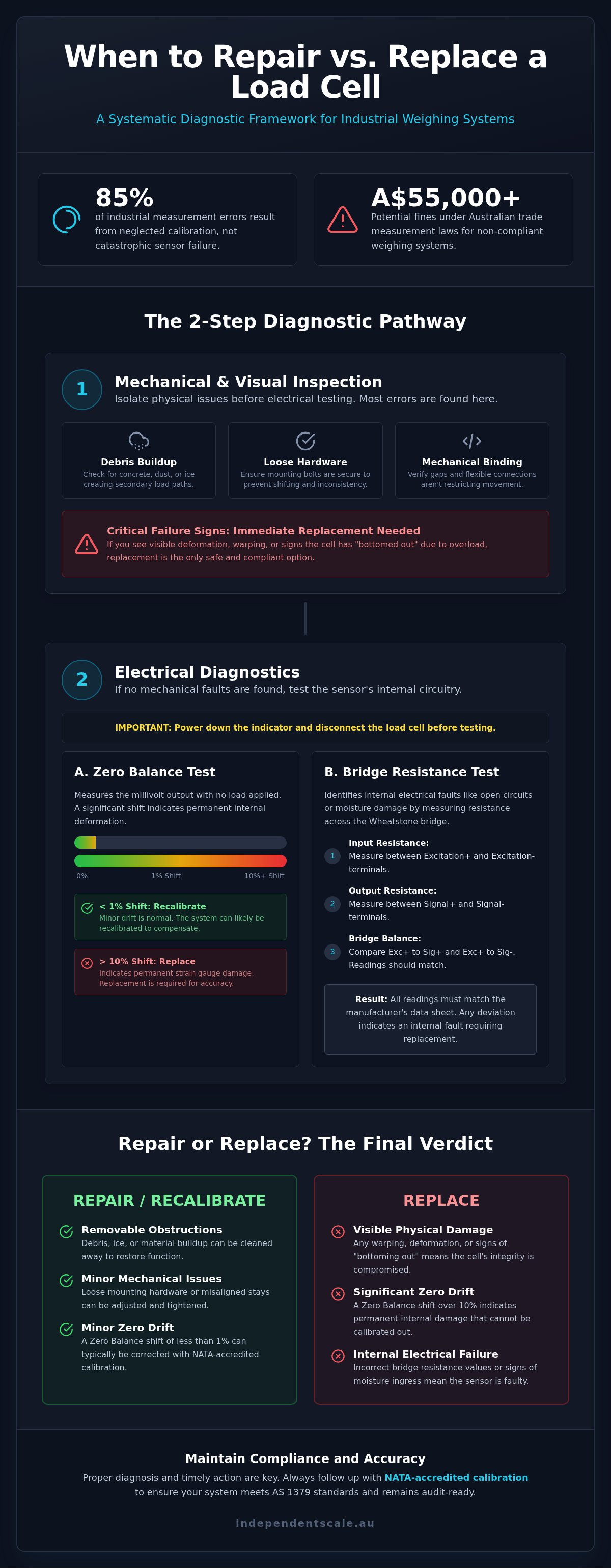
Before conducting complex electrical diagnostics, you must verify the mechanical integrity of the weighing system. A significant percentage of reported inaccuracies stems from external interference rather than internal sensor failure. You should begin by clarifying what is a load cell in your specific application; it's a precision transducer that requires unobstructed deflection to provide an accurate signal. Since 85% of industrial measurement errors are the result of neglected maintenance and calibration schedules, identifying physical faults is the most efficient way to restore accuracy.
Systematic inspections should focus on the following components:
- Debris Buildup: Accumulation of concrete, dust, or ice around the load cell can create a secondary load path, bypassing the sensor.
- Loose Hardware: Mounting bolts that have vibrated loose cause shifting and inconsistent readings during batching.
- Anti-Rotation Stays: Check rods and stays must be loose enough to allow vertical movement but tight enough to prevent excessive lateral sway.
Detecting Mechanical Binding and Friction
Perform a thorough gap check between the hopper and the support frame. Even a small piece of debris or a hardened layer of paint can bridge the gap, causing "binding" where the force is diverted away from the sensor. In Australian concrete batching plants, material buildup is a frequent cause of non-compliance with AS 1379. You must ensure that flexible connections, such as those on inlet and outlet pipes, remain pliable and aren't pulling or pushing on the vessel. Corroded mounting assemblies often restrict the necessary movement of the cell, leading to non-linear readings that cannot be corrected through simple calibration.
Inspecting Load Cell Mounting Assemblies
Structural levelness is vital for accurate weight distribution across all support points. If a base plate isn't level or the mounting assembly is misaligned, the load cell will experience "side loading," which introduces significant error. Look for signs that the cell has "bottomed out," which occurs when the overload protection is set incorrectly or the structure has shifted. This physical damage is a primary indicator of when to repair vs replace a load cell. If the mounting hardware is warped or the load cell body shows visible deformation, replacement is usually the only viable option to maintain NATA-accredited standards. For systems requiring new hardware, upgrading to modern tank and silo weighing assemblies can prevent future mechanical failures and clarify when to repair vs replace a load cell by providing more robust overload protection.
Electrical Diagnostics: Testing the Load Cell Bridge
Once you've ruled out mechanical obstructions, you must isolate the electrical components to pinpoint the failure. Safe diagnostic procedures require powering down the weighing indicator and physically disconnecting the load cell from the junction box or terminal block. This prevents the multimeter from reading resistance through the indicator's circuitry, which would yield inaccurate data. A high-quality digital multimeter is necessary for these checks; standard industrial sensors operate on precise millivolt signals that require sensitive measurement tools.
Performing a Zero Balance Test
Zero Balance is the output of the load cell when no load is applied. To perform this test, ensure the cell is disconnected from the indicator but receives its rated excitation voltage. Measure the millivolt output across the signal wires using your multimeter. A healthy cell should return a value extremely close to zero, typically within the manufacturer's specified tolerance. If the reading shows a 1% shift from the original factory zero balance, the system can often be recalibrated to compensate. However, a shift of 10% or more indicates permanent deformation of the internal strain gauge or the spring element itself. This level of damage provides a clear answer for when to repair vs replace a load cell; significant physical deformation typically necessitates a full replacement to maintain NATA calibration compliance.
Measuring Bridge Resistance
Measuring resistance across the Wheatstone bridge identifies internal electrical faults such as open circuits or moisture ingress. You should follow these steps using the ohms setting on your multimeter:
- Input Resistance: Measure between the Excitation + and Excitation - terminals.
- Output Resistance: Measure between the Signal + and Signal - terminals.
- Bridge Balance: Compare the resistance between Excitation + and Signal +, then Excitation + and Signal -. The readings should be identical.
These values must match the manufacturer's data sheet, usually within a tolerance of +/- 1 to 5 ohms. An 'infinite' reading indicates an open circuit, while a significantly lower reading suggests a short. This data helps determine when to repair vs replace a load cell, as internal bridge imbalances often signal terminal failure. If you detect moisture ingress through insulation testing, measuring resistance between the shield and any bridge wire, the unit's hermetic seal is likely compromised. For complex faults that require more than a simple terminal cleaning, professional load cell calibration and diagnostic services are the most reliable path to restoring your system's accuracy.
Identifying Faults in Cables and Junction Boxes
Signal integrity depends entirely on the condition of the cabling and the summing environment. In harsh Australian industrial sites, cables are frequently exposed to physical abrasion, chemical corrosion, and rodent damage. Rodents often chew through polyurethane or PVC jackets, exposing the internal wiring to the elements. Once the jacket is breached, moisture wicking becomes a critical risk. Capillary action can pull water through the cable length directly into the load cell or the junction box, causing erratic signal fluctuations that are difficult to trace.
Testing signal consistency across multiple cells is the next logical step. If you've performed the bridge resistance checks mentioned previously and found the sensors healthy, the fault likely resides in the summing system. Determining when to repair vs replace a load cell often hinges on whether the signal instability originates within the sensor itself or the interconnecting hardware. Splicing a damaged cable is a temporary measure that often introduces resistance imbalances; for long term reliability and AS 1379 compliance, cable replacement or cell replacement is the standard professional recommendation.
Junction Box Integrity and Summing Boards
The junction box is the central hub where individual load cell signals are summed into a single output for the indicator. You must inspect the internal summing board for signs of terminal corrosion or loose wire connections. Even a slightly loose excitation wire can cause significant weight "drifting." To isolate a failure in a multi-cell system, perform a Corner Test. This involves placing a known weight over each load cell individually and comparing the readings. If one corner provides a significantly different value, you've isolated the fault to that specific cell or its corresponding terminal. If the box shows signs of moisture ingress or PCB oxidation, upgrading to high quality industrial junction boxes with superior sealing is necessary to prevent recurring downtime.
Cable Shielding and Signal Interference
Electromagnetic Interference (EMI) and Radio Frequency Interference (RFI) are common causes of unstable readings in environments with large motors or high voltage power lines. You must verify that the cable shielding is continuous and properly grounded at the indicator end only. Improper grounding creates ground loops, which introduce "noise" into the millivolt signal. If you find that the cable shielding is brittle or compromised by UV exposure, the risk of signal interference increases. While a damaged jacket can sometimes be resealed, a compromised shield usually justifies a full cable replacement. This diagnostic step helps clarify when to repair vs replace a load cell; if the internal wiring is intact but the external shielding is failed, a professional cable replacement may restore the system without the need for a new sensor.
Interpreting Performance Issues: Drift and Inaccuracy
Performance-based diagnostics are necessary when a weighing system passes physical and electrical resistance tests but continues to produce unreliable data. You must differentiate between zero drift and span drift to isolate the root cause. Zero drift refers to a shift in the scale's zero point over time, often caused by material buildup or temperature changes. Span drift occurs when the scale's accuracy changes as the load increases, suggesting a change in the load cell's sensitivity. These issues directly impact your ability to maintain AS 1379 compliance, especially in high-volume concrete batching plants where precision is mandatory.
Hysteresis and non-repeatability are more severe indicators of internal failure. Hysteresis is the difference in output for the same applied load depending on whether the weight was increasing or decreasing. If your scale doesn't return to zero after unloading, and you've ruled out mechanical binding, the internal spring element has likely suffered permanent deformation. Non-repeatability, where the scale provides different readings for the same weight applied multiple times, often signals that the internal strain gauge has reached the end of its fatigue life. These symptoms are primary factors when determining when to repair vs replace a load cell.
Diagnosing Weight Drift
Weight drift is often characterized by a creeping reading on the indicator that fails to stabilize. In the Australian climate, thermal expansion is a common culprit for drift in large structures like silos. As the metal structure expands in the heat, it can exert parasitic forces on the weighing assembly. If your readings fluctuate significantly between morning and afternoon, environmental compensation may be failing. You can find more technical details on environmental factors in The Essential Guide to Industrial Load Cells. If the drift persists in a climate-controlled environment, the fault likely lies in the bridge's internal temperature compensation resistors.
Repeatability and Linearity Checks
To verify linearity, apply known weights in 25% increments up to the scale's full capacity. A healthy system should show a linear progression in millivolt output. Non-linear results often point to internal sensor damage or structural deflection, where the mounting plates flex under heavy loads. You should also verify if the performance issue originates in the indicator or display by using a load cell simulator to provide a clean signal to the electronics. If the indicator remains stable during the simulation, the fault is isolated to the load cell. Deciding when to repair vs replace a load cell becomes straightforward at this stage; linear drift is often correctable through professional calibration, but non-repeatable errors usually require a full unit replacement. If your system is failing repeatability tests, contact our team for professional on-site diagnostics to prevent further production downtime.
Professional Repair and NATA Calibration Compliance
DIY diagnostics are effective for identifying obvious mechanical or cabling faults, but they cannot replace professional verification. Once you've determined that the fault isn't external, you must decide when to repair vs replace a load cell based on technical data and regulatory requirements. If a sensor shows internal bridge imbalances or significant zero drift, attempting a field repair often compromises the hermetic seal. For industrial applications in Sydney and Melbourne, the transition from troubleshooting to professional service is necessary to ensure the system remains compliant with Australian trade measurement laws.
Professional intervention provides a defensible audit trail. While a basic calibration might restore temporary accuracy, it lacks the technical rigour required for high-stakes industrial environments. Regular preventative maintenance identifies aging sensors before they fail, allowing for planned replacements rather than emergency shutdowns that halt production.
NATA Accreditation and ISO/IEC 17025 Standards
In Australia, NATA accreditation is the benchmark for technical competence in calibration. ISO/IEC 17025 compliance ensures that the testing laboratory operates with validated methods and calibrated master equipment. This accreditation is critical for legal-for-trade compliance, where measurement errors can lead to fines exceeding A$55,000. Independent Scale Service provides on-site calibration for hoppers and silos, ensuring that your equipment meets these international standards. You can find more information on these requirements in Calibration Services: The Authoritative Guide.
Concrete Batching Plant Compliance
Concrete production requires extreme precision to ensure structural integrity and material consistency. AS 1379:2026 is the mandatory standard for the specification and supply of concrete in Australia. AS 1379 requires regular, documented calibration of all weighing components in a concrete plant. Troubleshooting cement and aggregate hoppers often reveals that environmental wear has degraded the sensors beyond the point of simple adjustment. Professional batching plant calibration is the final step in the diagnostic process. It confirms that any repaired or replaced components function within the strict tolerances required by the standard.
The logic for when to repair vs replace a load cell in a batching plant often depends on the age of the equipment. Most industrial load cells have a reliable lifespan of 8 to 10 years; if a cell is nearing this limit and showing signs of non-linearity, replacement is the more cost-effective choice. Replacing a single faulty cell in a multi-cell system often requires matching the output of the remaining sensors, a process that demands professional expertise to maintain system-wide accuracy.
Optimising Weighing Accuracy and Regulatory Compliance
Maintaining industrial weighing systems requires a methodical approach to identifying faults. By isolating mechanical binding and performing bridge resistance checks, you can accurately determine when to repair vs replace a load cell before production halts occur. While DIY diagnostics provide an initial assessment, achieving full AS 1379 compliance requires professional verification and documented proof of accuracy. Neglecting these standards risks material waste and potential fines exceeding A$55,000 under Australian trade measurement laws.
Independent Scale Service provides the technical expertise necessary to restore your systems to peak performance. Our expert technicians in Sydney and Melbourne are NATA accredited to ISO/IEC 17025, ensuring that every calibration meets the highest regulatory standards for concrete batching and silo applications. We focus on minimising your downtime through responsive, methodical service that prioritises reliability. Contact Independent Scale Service for NATA-Accredited Load Cell Repair & Calibration to secure your facility's compliance and operational efficiency. We're ready to assist with your next scheduled maintenance or emergency diagnostic requirement.
Frequently Asked Questions
How do I know if my load cell is bad?
Erratic weight readings, failure to return to zero, and non-linear output are primary indicators of a failing sensor. You should use a digital multimeter to check for internal resistance imbalances or a zero balance shift exceeding 10% of the rated output. If these electrical signatures are present, it's a clear signal of when to repair vs replace a load cell. Physical signs like visible deformation or corrosion also confirm the unit is compromised.
Can a damaged load cell cable be repaired?
Temporary repairs such as splicing can be performed, but they're generally discouraged in industrial settings. Splicing often introduces moisture ingress points and alters the cable's resistance, which leads to signal instability and weight drifting. For facilities requiring AS 1379 compliance, replacing the entire cable or the load cell unit is the standard professional recommendation. This ensures signal integrity is maintained and prevents recurring faults caused by environmental exposure in harsh Australian worksites.
What is the most common cause of load cell failure?
Environmental factors and physical abuse are the leading causes of failure in industrial sensors. Moisture ingress through compromised seals or damaged cable jackets accounts for a high percentage of technical faults. Overloading, shock loading, and lightning strikes also cause permanent deformation of the internal strain gauge. Research shows that 85% of measurement errors result from neglected calibration schedules rather than total sensor failure, which underscores the necessity of regular NATA-accredited maintenance.
How do I test a 4-wire vs. 6-wire load cell?
Both types are diagnosed using bridge resistance measurements between the excitation and signal leads. A 4-wire cell contains excitation (+/-) and signal (+/-) leads, while a 6-wire cell adds two "sense" leads to compensate for voltage drops over long distances. When testing a 6-wire cell, the sense leads should show near-zero resistance against their respective excitation leads. Always ensure the cell is disconnected from the indicator before using a multimeter to measure ohms.
Why is my scale reading different weights in different corners?
This variation, known as corner error, typically indicates a faulty load cell or mechanical binding at one support point. It can also stem from an imbalanced summing board within the junction box. You should perform a corner test by placing a known weight over each load cell individually. If one corner deviates significantly from the others, inspect that specific assembly for debris buildup, loose mounting bolts, or internal electrical shifts in the Wheatstone bridge.
Does my weighing system need NATA calibration after a load cell replacement?
Yes, NATA-accredited calibration is mandatory following any major component replacement to ensure ongoing compliance with ISO/IEC 17025. Replacing a load cell fundamentally changes the system's electrical output. Without professional calibration, the scale cannot be certified for legal-for-trade use or meet AS 1379 standards for concrete batching operations. This process provides the defensible audit trail required by Australian regulatory bodies and ensures the accuracy of your batching data.
What tools do I need for basic load cell troubleshooting?
A high-quality digital multimeter with millivolt sensitivity is the most critical tool for electrical diagnostics. You also require standard hand tools such as wrenches and screwdrivers to inspect mounting hardware and junction box terminals. For performance verification, a set of certified test weights is necessary to check linearity and repeatability. These tools allow you to perform initial bridge resistance measurements and gap checks before deciding when to repair vs replace a load cell.
How often should industrial load cells be professionally calibrated?
Most industrial weighing systems require professional calibration every 6 to 12 months, depending on the operational environment. Concrete batching plants must adhere to the specific intervals defined in AS 1379 to maintain legal compliance. Harsh environments with high moisture or chemical exposure often necessitate more frequent inspections. Regular NATA-accredited service identifies aging sensors before they fail completely, significantly reducing the risk of costly production halts and regulatory non-compliance fines.
