


How to Test a Load Cell for Accuracy: An Industrial Troubleshooting Guide
A single faulty load cell can halt production and trigger an immediate non-compliance report under AS 1379 standards. When batch weights drift or scales refuse to zero, the priority is to identify the root cause without replacing functional components. You understand that unexpected downtime is a significant risk to operational profitability; it's a problem that requires a methodical, technical solution. This guide explains how to test a load cell for accuracy by systematically isolating electrical faults from mechanical interference.
You'll learn to perform professional diagnostics, including checking for insulation resistance above 5 GΩ and verifying that zero balance remains within 1% of the full-scale output. While basic multimeter checks can identify a total bridge failure, verifying accuracy for a NATA-accredited audit requires a rigorous gravimetric approach. We will outline the specific diagnostic path to minimize equipment downtime and ensure your systems remain compliant with the 2026 NIST Handbook 44 and OIML R 60 international standards.
Key Takeaways
- Identify mechanical interference and binding in mounting assemblies before proceeding to electrical diagnostics.
- Learn how to test a load cell for accuracy using a multimeter to verify bridge resistance and isolate intermittent wiring faults via the "Tap Test".
- Detect moisture-related signal drift by measuring insulation resistance with a megohmmeter to find leakage paths to earth.
- Understand the necessity of NATA-accredited gravimetric testing for verifying compliance with AS 1379 and ISO/IEC 17025 standards.
- Establish a clear diagnostic sequence to differentiate between sensor failure and system-wide interference to minimize operational downtime.
Understanding Load Cell Accuracy and Common Failure Modes
Load cell accuracy is defined as the transducer's ability to provide a linear electrical output that is directly proportional to the applied mechanical force. For a device to be considered accurate, its output must stay within specific tolerance bands across its entire rated capacity. Before learning What is a load cell? and how it functions, technicians must understand that a "working" cell is not necessarily an "accurate" one. A cell might still produce a signal and respond to weight, but if that signal deviates by even 0.5% from the true value, it fails industrial standards. Precision is binary in an audit environment; equipment is either compliant or it isn't.
Industrial environments are harsh on sensitive electronics. Several factors lead to accuracy degradation over time:
- Overloading: Stressing the internal strain gauge beyond its elastic limit, which causes permanent zero-shift.
- Moisture Ingress: Humidity or direct water entry into the cable entry point or sensing area, leading to insulation resistance failure.
- Chemical Corrosion: Deterioration of the housing or seals in washdown or acidic environments, compromising the structural integrity of the sensor.
For concrete batching plants, maintaining these units is a regulatory requirement under AS 1379. This standard mandates rigorous verification to ensure batch consistency and structural integrity across every mix. Failure to meet these standards doesn't just risk production quality; it risks your accreditation.
Why Accuracy Matters in Industrial Weighing
The financial cost of inaccuracy is often hidden in raw material giveaway. If a plant producing 50,000 cubic meters of concrete annually has a 1% over-weighing error on cement, the lost revenue can exceed $40,000 based on current material costs. Safety is equally critical. In crane scales or silo weighing, an inaccurate reading can lead to catastrophic structural failure or dangerous overfills. For a deeper look at the technology behind these sensors, refer to The Essential Guide to Industrial Load Cells. Accurate measurement isn't just about compliance; it's about protecting your bottom line and your personnel.
Signs Your Load Cell is Losing Calibration
Identifying the symptoms of failure is the first step in determining how to test a load cell for accuracy. Common indicators include "drifting," where the weight display changes continuously while the vessel is empty. You might also notice "hunting," where the digital indicator fluctuates rapidly and fails to settle on a stable reading. Non-linearity is another red flag; the scale may appear accurate at low weights but show significant errors as the load increases. Differentiating between an intermittent electrical fault and a permanent mechanical zero-shift is essential for effective troubleshooting. If the zero balance has shifted by more than 1% of the full-scale output, the cell has likely suffered physical damage.
Preliminary Physical and Mechanical Inspections
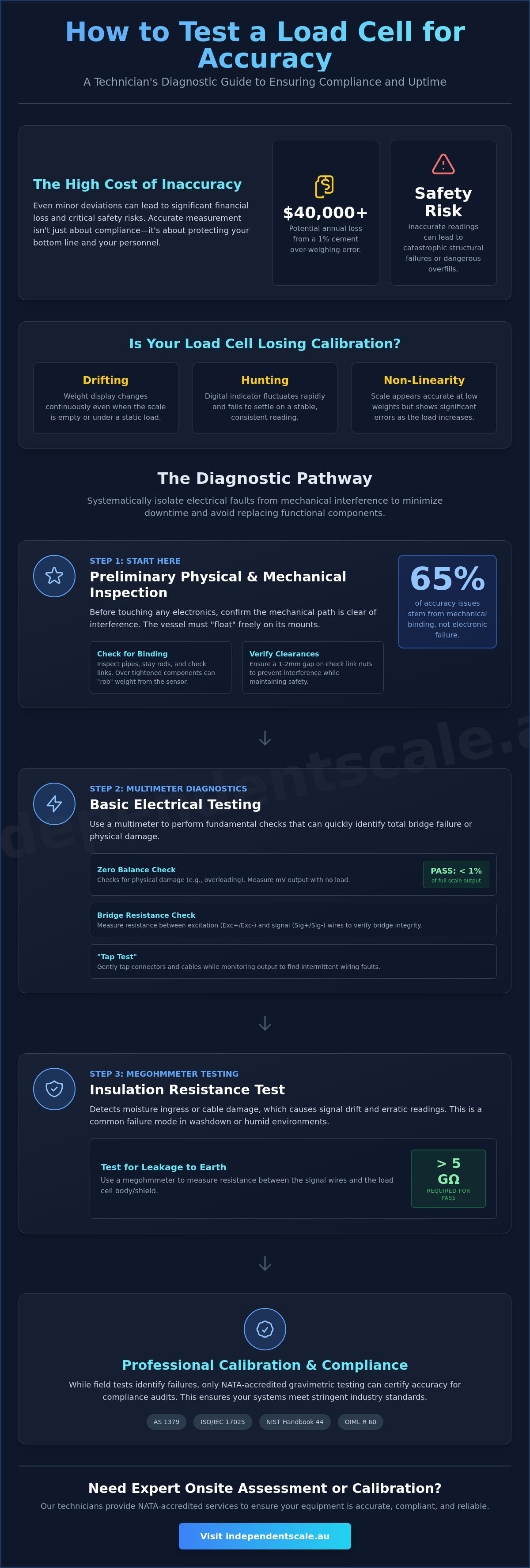
Before investigating electrical signals, you must confirm the mechanical path is clear. In Australian industrial environments, approximately 65% of accuracy issues stem from mechanical binding rather than electronic failure. The "mechanical path" refers to the unobstructed flow of force from the load, through the vessel, and directly into the sensor. If any secondary path exists, such as a jammed stay rod or a stiff pipe, the weight reading will be consistently inaccurate. To effectively troubleshoot common load cell issues, start by ensuring the vessel is "floating" freely on its mounts.
Stay rods and check links are critical for safety and stability in high-capacity silos. However, if these components are over-tightened or misaligned, they create friction that "robs" weight from the load cell. A gap of 1mm to 2mm is typically required on check link nuts to prevent interference while maintaining structural safety. If you suspect structural issues are compromising your data, our team provides expert onsite assessments to identify these mechanical bottlenecks.
Environmental factors like wind and temperature also distort accuracy. A 25 km/h wind gust against a vertical silo can create significant "lift" or lateral pressure, leading to erratic readings. Similarly, thermal expansion of large steel structures can cause binding if the mounting hardware doesn't allow for lateral movement. These factors must be ruled out before condemning the electronics.
Visual Inspection Checklist
- Debris Build-up: Check the "dead space" between the load cell and its mounting plate. Accumulated concrete dust, stones, or ice can create a physical bridge that bypasses the sensor.
- Corrosion: Inspect the load cell body and cable entry points. Significant pitting or rust on the load-bearing surfaces can alter the way force is distributed through the strain gauge.
- Orientation: Verify that the cell is level and correctly oriented. Most cells have a "direction of load" arrow; if installed upside down or at an angle, the output will be non-linear.
Identifying Mechanical Interference and Binding
Determining how to test a load cell for accuracy requires checking for rigid connections. Rigid conduit or stiff piping connected to a weighing hopper acts like a spring, either supporting some of the weight or pushing down on the vessel. Use flexible couplings for all intake and discharge points. Additionally, check for "bottoming out" where the load rests on a safety stop or secondary structure instead of the cell. For complex silo setups, professional Hopper Calibration Services are essential to verify that the entire mechanical assembly is functioning as intended under full load conditions.
Electrical Testing: Using a Multimeter for Fault Diagnosis
Electrical testing is the next phase after confirming the mechanical integrity of the system. While a multimeter cannot verify metrological accuracy to NATA standards, it's the most effective tool for identifying catastrophic electrical failure. To understand how to test a load cell for accuracy at the component level, you must evaluate the health of the internal Wheatstone bridge. This involves measuring resistance and millivolt output to ensure the sensor is responding within its designed parameters.
Start by measuring the excitation voltage at the load cell terminals while the indicator is powered. Typical excitation ranges from 5V to 15V DC. If this voltage is absent or fluctuating, the issue likely lies with the indicator or the cabling rather than the sensor itself. Once power is confirmed, perform a "Tap Test." While monitoring the millivolt output, gently tap the load cell body or wiggle the cable. Any sudden jumps in the reading indicate a loose internal connection or a break in the cable shield. This simple check often reveals faults that static tests miss.
Resistance Testing: Input, Output, and Bridge
Set your multimeter to the Ohms (Ω) setting to check the continuity of the internal circuit. Measure the resistance between the excitation leads (Input) and the signal leads (Output). For standard strain gauge sensors, these values are typically 350Ω, 700Ω, or 1000Ω. You should compare these readings against the technical specifications found on our Load Cells collection data sheets. A deviation of more than ±5% from the manufacturer’s specification indicates that the strain gauge has been compromised. A reading of "OL" or infinity suggests an open circuit; very low resistance indicates a short. These resistance checks are essential for diagnosing how to test a load cell for accuracy before committing to a full recalibration.
Measuring Zero Balance and Output Signal
Zero balance is the signal the cell produces when no load is applied. With the excitation power on, measure the DC millivolts across the signal wires. A healthy cell should have a zero balance within ±1% of its full-rated output. For example, if a cell has a 2mV/V sensitivity and 10V excitation, its full-scale output is 20mV. A zero balance exceeding 0.2mV suggests a "Zero Shift" caused by physical deformation from a prior overload event. The mV/V ratio represents the millivolts of signal produced for every volt of excitation at full capacity. If your zero balance is significantly out of range, the cell is permanently damaged and requires replacement to restore system accuracy. This diagnostic process provides a clear path to identifying faulty components without guesswork.
Troubleshooting Signal Drift and Environmental Interference
Moisture ingress within a junction box is the leading cause of signal drift in industrial weighing systems. When humidity or liquid enters the enclosure, it creates high-resistance leakage paths between the excitation and signal terminals. This results in "drifting," where the weight display fluctuates without any change in physical load. To understand how to test a load cell for accuracy under these conditions, you must look beyond the sensor itself and evaluate the integrity of the entire signal path. Utilizing high-quality Junction Boxes and Surge Arrestors is a critical defense against these environmental variables.
Identifying Insulation Resistance Issues
Insulation resistance testing identifies "leakage" to earth that a standard multimeter often misses. Using a megohmmeter (megger), you should measure the resistance between the cable shield and all other wires, and between the load cell body and the bridge wires. A healthy load cell typically shows an insulation resistance of 5 Giga-Ohms (GΩ) or higher. If the reading drops below 2 GΩ, moisture has likely compromised the internal strain gauge or the cable. You must never apply high voltage from an insulation tester directly across the bridge wires (e.g., excitation + to excitation -), as this will instantly destroy the sensitive strain gauge. Erratic readings that worsen during humid weather or after washdown procedures are classic symptoms of failed insulation.
Managing Electrical Noise and Surge Damage
Radio Frequency Interference (RFI) and Electromagnetic Interference (EMI) can induce noise in low-voltage millivolt signals, causing the indicator to "hunt" for a stable weight. This is common in plants where load cell cables run parallel to high-voltage power lines or near Variable Frequency Drives (VFDs). Ensure all cables are shielded and that the shield is grounded at only one end to prevent ground loops. Surge damage is another frequent failure mode; lightning strikes or welding on the scale structure can "blow" the internal bridge. If you detect a sudden, permanent shift in zero balance after maintenance or a storm, the cell likely has physical bridge damage. In environments with high electrical noise, installing Conditioners and Transmitters can help stabilize the signal before it reaches the indicator. For persistent accuracy issues that defy basic troubleshooting, consult with our technical team to arrange a site-specific interference audit.
Professional Calibration vs. DIY Testing: Ensuring Compliance
While a multimeter is an essential tool for initial fault diagnosis, it's incapable of verifying metrological accuracy. Understanding how to test a load cell for accuracy requires a clear distinction between component-level troubleshooting and system-wide verification. A load cell can pass every electrical resistance test yet still fail to provide linear readings under load. DIY methods are excellent for identifying "dead" cells or cabling faults, but they cannot replace the rigorous standards required for industrial compliance and audit purposes.
Professional verification relies on NATA-accredited test masses and traceable procedures. For industries like civil construction and food processing, the "simulated calibration" provided by many digital indicators is insufficient. This method only injects a theoretical millivolt signal; it doesn't account for mechanical friction, structural deflection, or environmental interference. True accuracy is only confirmed through gravimetric testing, where known physical weights are applied to the system. For specialized operations, such as Concrete Batching Plant Calibration, this physical verification is a non-negotiable regulatory requirement.
The Limits of Multimeter Testing for Accuracy
A load cell can exhibit perfect bridge resistance and still have poor linearity or hysteresis. This often happens when the internal strain gauge has partially debonded or when the metal body has suffered microscopic fatigue. These issues only manifest when the sensor is under physical stress. Because of this, electrical tests are only half of the diagnostic equation. You can learn more about the technical requirements for different industries in Calibration Services: The Authoritative Guide. Relying solely on a multimeter to determine how to test a load cell for accuracy risks leaving your plant vulnerable to significant weighing errors that bypass basic electrical checks.
NATA Accreditation and AS 1379 Compliance
In Australia, NATA accreditation to ISO/IEC 17025 is the gold standard for weighing accuracy. This accreditation ensures that the equipment and methods used by a service provider are technically competent and yield reliable results. Under AS 1379, concrete batching plants must adhere to strict 6-month or 12-month calibration cycles to maintain their certification. Independent Scale Service brings over 30 years of experience to these high-stakes environments, servicing 98% of concrete plants across Sydney. We recommend using DIY checks for immediate troubleshooting to minimize downtime, but always rely on professional, NATA-accredited technicians for your scheduled compliance and certification needs. This dual approach ensures your equipment stays operational while meeting all legal and industrial standards.
Securing Long-Term Industrial Weighing Accuracy
Maintaining precise measurements is a continuous process that demands both technical knowledge and specialized equipment. You've seen that while 65% of weighing issues are mechanical, electrical faults like moisture ingress or bridge deformation require precise tools to isolate. Now that you understand how to test a load cell for accuracy through both physical inspections and multimeter diagnostics, you can effectively troubleshoot immediate failures. However, maintaining compliance with AS 1379 for concrete plants or meeting ISO/IEC 17025 requirements for audited facilities requires professional verification.
Independent Scale Service provides the technical expertise and NATA-accredited test masses needed to certify your systems. We offer 24/7 emergency repair support across Sydney and Melbourne to ensure your production lines remain operational. Don't let inaccurate batching compromise your structural integrity or financial performance. Request an On-Site NATA Accredited Calibration Service today to ensure your facility remains fully compliant and accurate.
Frequently Asked Questions
Can I test a load cell with a standard digital multimeter?
Yes, a multimeter is the primary tool for initial diagnostics. You can measure bridge resistance and zero balance to identify catastrophic failures. However, this method only identifies if a cell is "dead" or "alive." When determining how to test a load cell for accuracy for compliance purposes, a multimeter cannot replace a NATA-accredited gravimetric test using certified test masses.
What is the most common cause of load cell failure?
Moisture ingress into the junction box or cable entry point is the most frequent cause of failure. This leads to insulation resistance dropping below the ideal 5 GΩ threshold. Physical overloading is the second most common cause; it permanently deforms the internal strain gauge and creates an unrecoverable zero shift exceeding 1% of the full-scale output.
What is load cell "drift" and how do I fix it?
Signal drift is a continuous fluctuation in the weight reading while the load remains constant. This is almost always an electrical issue caused by moisture or temperature-induced resistance changes. You fix it by inspecting the junction box seals and measuring insulation resistance with a megohmmeter. If the reading is below 2 GΩ, the sensor or cable likely requires replacement.
How much mV signal should a healthy load cell produce?
A healthy cell produces a millivolt (mV) signal based on its sensitivity rating, usually 2mV/V or 3mV/V. With a 10V excitation voltage, a 2mV/V cell will output exactly 20mV at its maximum rated capacity. At zero load, the signal should remain within ±1% of this full-scale output (±0.2mV) to be considered functional for industrial use.
Is it possible to repair a damaged load cell?
Internal repairs are not possible once the strain gauge or the hermetic seal is compromised. Because the sensor is a precision-machined component, any attempt to fix the internal bridge will destroy its linearity and repeatability. You can repair external faults like damaged cables or corroded junction boxes, but a damaged sensor body must be replaced to ensure system accuracy.
How often should industrial load cells be calibrated for accuracy?
Industrial load cells should undergo professional calibration at least once every 12 months. Facilities operating under AS 1379 standards for concrete production often require 6-month intervals to maintain accreditation. High-intensity environments or those with strict ISO/IEC 17025 requirements may necessitate more frequent verification to prevent costly production errors and raw material giveaway.
What is the difference between a 4-wire and 6-wire load cell test?
6-wire load cells include two additional "sense" wires that monitor the actual voltage reaching the bridge. This allows the indicator to compensate for voltage drops caused by resistance in long cable runs. When performing how to test a load cell for accuracy on a 6-wire system, you must verify that the sense voltage matches the excitation voltage at the terminal blocks.
What is AS 1379 and does it apply to my weighing equipment?
AS 1379 is the mandatory Australian Standard for concrete specification and manufacture. It applies to all weighing equipment within a concrete batching plant, including cement, aggregate, and water scales. Compliance requires regular NATA-accredited testing to ensure that batch weights remain within the strict tolerances defined by the standard to ensure structural mix consistency.
