


Industrial Load Cell Installation: Australian Guide
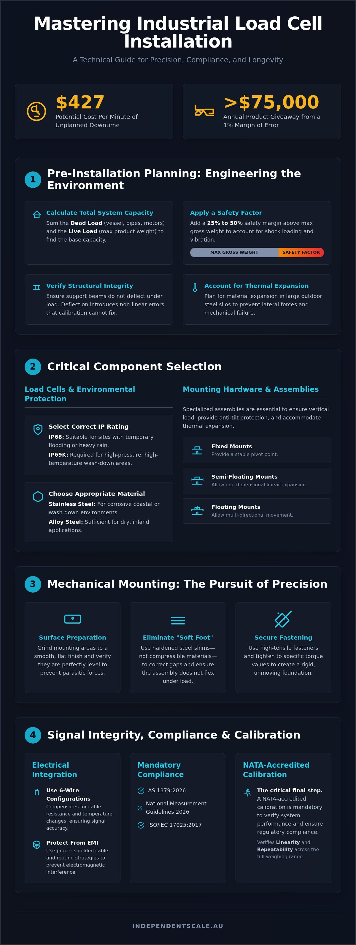
Unplanned downtime for Australian manufacturers can cost as much as $427 per minute. In high-volume operations like concrete batching or silo management, a 1% margin of error often results in over $75,000 in annual product giveaway. You understand that precision isn't just a preference; it's a financial necessity. However, even the most sophisticated sensors fail when industrial load cell installation is treated as a secondary concern rather than a technical discipline.
System drift and moisture ingress frequently lead to non-compliance with AS 1379:2026 and the National Measurement Guidelines 2026. This article provides the technical roadmap required to master these installations and ensure your equipment passes NATA audits every time. We'll examine the mechanical alignment protocols, environmental shielding strategies, and the mandatory accreditation standards necessary to extend your load cell lifespan and maintain ISO/IEC 17025:2017 compliance. Following these procedures ensures that your weighing system remains a reliable asset rather than a source of regulatory risk.
Key Takeaways
- Learn how to engineer a stable weighing environment by accurately calculating dead loads and verifying structural integrity before industrial load cell installation begins.
- Master mechanical mounting techniques, including precision shimming and leveling, to eliminate lateral movement and prevent measurement errors.
- Understand the technical advantages of 6-wire configurations and cable routing strategies to protect signal integrity from electromagnetic interference.
- Ensure your system meets AS 1379:2026 standards and National Measurement Guidelines to guarantee compliance during industrial audits.
- Discover the critical necessity of post-installation NATA-accredited calibration to verify linearity and repeatability across the full weighing range.
Pre-Installation Planning: Engineering the Weighing Environment
Successful industrial load cell installation requires rigorous engineering before equipment arrives on-site. You must calculate the total system capacity by summing the dead load (the weight of the empty vessel, piping, and motors) and the live load (the maximum product weight). Standard practice in Australian industrial environments suggests a safety factor of at least 25% to 50% above the maximum gross weight to account for shock loading and vibration. To understand the underlying technology of these sensors, it helps to review the technical definition of What is a Load Cell? as a transducer that converts mechanical force into a standardized electrical output.
Engineers must also assess the structural integrity of support beams. If the mounting surface deflects under load, it introduces non-linear errors that calibration cannot fully resolve. For large-scale outdoor silo installations, thermal expansion is a critical variable. A steel silo can expand significantly in the heat of an Australian summer; without proper planning, this expansion exerts lateral forces on the sensors, leading to system drift or mechanical failure. Selecting the correct sensor type, whether it's a shear beam, canister, or S-type, is the first step in mitigating these environmental risks.
Load Cell Capacity and Environmental Ratings
Selecting the correct sensor type depends on the vessel's geometry and the site's environmental conditions. Shear beam cells are standard for many platforms, while canister cells are preferred for high-capacity silos. In Australian coastal regions or wash-down areas, material selection is non-negotiable. Stainless steel sensors offer the necessary corrosion resistance, whereas alloy steel may suffice for dry, inland sites. Environmental protection is measured by IP ratings. IP68-rated sensors are suitable for sites prone to temporary flooding or heavy rain. However, food processing or concrete batching plants often require IP69K-rated equipment to withstand high-pressure, high-temperature cleaning cycles.
Mounting Hardware and Weighing Assemblies
The use of specialized tank and silo weighing assemblies is essential for protecting sensors from destructive forces during industrial load cell installation. These assemblies serve three primary functions: they ensure vertical load application, provide anti-tilt protection, and accommodate thermal expansion. Different mounting configurations are used based on the vessel type:
- Fixed Mounts: These provide a pivot point, typically used on horizontal tanks where only one end is weighed.
- Semi-Floating Mounts: These allow for one-dimensional movement to accommodate linear expansion.
- Floating Mounts: These allow for multi-directional movement while maintaining vertical alignment, essential for large silos.
Correct hardware selection ensures horizontal constraint without interfering with the vertical force required for accurate measurement. This balance prevents the system from binding, which is a common cause of measurement inaccuracy in poorly designed weighing systems.
Mechanical Mounting: Achieving Precision Alignment
Precision in industrial load cell installation is won or lost during the mechanical mounting phase. Unlike controlled laboratory settings, industrial sites like concrete batching plants often feature uneven concrete pads or structural steel that isn't perfectly true. You must grind the mounting area to a smooth finish and verify its level before securing the base plates. Any lateral movement in these plates introduces parasitic forces that compromise the system's integrity and lead to inconsistent weighing data. Securing the mounting plates requires high-tensile fasteners tightened to specific torque values to ensure a rigid foundation that won't shift under the stress of full-capacity loads.
Surface Preparation and Shimming
Structural unevenness frequently creates "soft foot" conditions, where one corner of a mounting assembly doesn't sit flush against the foundation. This gap causes the assembly to flex when weight is applied, producing non-linear results that are impossible to calibrate out. You should use hardened steel shims to correct these gaps rather than soft materials that compress over time. Use dial indicators to check surface parallelism across all mounting points. This step ensures the load cell remains perfectly vertical and free from the twisting forces that occur when mounting surfaces aren't parallel.
Load Introduction and Alignment
Accuracy depends on the load being applied strictly in the intended direction of the sensor's measurement axis. Side loads and eccentric loading, often caused by misaligned piping or thermal expansion, introduce significant measurement errors. Adhering to these strict mechanical tolerances ensures your system aligns with the technical standards upheld by the National Measurement Institute (NMI). During structural finishing, you must also protect the sensors from welding currents. High-amperage current passing through a load cell will fuse the internal strain gauges instantly, rendering the sensor useless.
Once you've verified the assembly is "level and plumb" using precision measurement tools, perform an initial corner check for multi-cell systems. This involves placing a known weight over each individual sensor to verify that the output remains consistent regardless of where the load is positioned on the vessel. If you're currently upgrading an existing plant or replacing failed sensors, sourcing the correct load cell supply is the foundation for achieving these precision standards.
Electrical Integration: Signal Integrity and Wiring
Signal integrity is the most common failure point after physical alignment is complete. Load cells output extremely low millivolt signals that are easily corrupted by electromagnetic interference (EMI). You must route all signal cables through dedicated, shielded conduits. Keep these runs at least 300mm away from AC power lines, heavy motors, and Variable Frequency Drives (VFDs). In large-scale Australian industrial sites, cable runs often exceed 20 meters, which introduces significant resistance. You should implement 6-wire configurations rather than standard 4-wire setups. The additional "sense" wires allow the weighing indicator to measure and compensate for voltage drops in real-time, ensuring the excitation voltage remains stable at the sensor head.
Cable Management and Protection
Protecting the cabling is as vital as protecting the sensor itself. Use flexible, liquid-tight conduits to prevent mechanical damage from site debris and stop moisture ingress. Never shorten load cell cables during industrial load cell installation. Manufacturers calibrate sensors based on the specific resistance of the supplied cable length. Cutting the cable changes this resistance and introduces temperature-related drift that complicates calibration. If you have excess cable, coil it loosely in a protected area away from power sources. Ensure all entry points are sealed with high-quality cable glands to prevent capillary action from drawing humidity into the sensitive internal circuitry.
Junction Box Configuration and Summing
Multi-cell systems, such as those found in silos or concrete batching plants, require a methodical approach to signal combining. You must use high-quality industrial junction boxes equipped with potentiometer-based summing boards. This hardware allows you to "balance" the output of each individual cell, ensuring the system provides a consistent reading regardless of where the load is positioned. Once the signals are summed, they often require conversion for modern control systems. Connecting signal conditioners and transmitters enables seamless PLC integration via 4-20mA or 0-10V outputs. Before proceeding to final testing, perform an excitation voltage check at the junction box to verify the integrity of the entire circuit.
In regional Australia, lightning strikes and power surges pose a significant threat to outdoor weighing equipment. You should implement dedicated earthing straps to bypass the load cell. This ensures that any electrical surge travels through the structural steel to the ground rather than through the sensor's delicate strain gauges. Proper earthing is a critical step in industrial load cell installation that prevents catastrophic equipment failure during storm events.
Compliance and Environmental Protection Standards
Compliance in Australia is governed by strict legislative instruments that were updated in early 2026. The National Measurement Guidelines 2026, which came into effect on 1 April 2026, dictate the framework for legal metrology and measurement accuracy. For any industrial operation, industrial load cell installation is not just a mechanical task but a regulatory requirement. Non-compliance with the National Measurement Act 1960 is a serious risk, with potential criminal penalties and fines reaching $170,000 per offense. Establishing a robust documentation trail from the moment of installation is essential for maintaining ISO/IEC 17025:2017 compliance and passing future NATA audits.
Australian Regulatory Requirements
The construction sector must pay particular attention to the updated AS 1379 on weighing accuracy. This standard, specifically AS 1379:2026 published on May 22, 2026, supersedes previous versions and sets the benchmark for concrete specification and supply. For systems used in trade, a two-part verification process by the National Measurement Institute is mandatory. You must maintain records of initial "As-Found" and "As-Left" data, which serve as the foundation for your NATA-accredited calibration history. This documentation proves that your measurement controls are adequate and prevents the 15% failure rate typically seen in ISO compliance reviews due to poor measurement management.
Harsh Environment Mitigation
Australian industrial sites present unique environmental challenges that can degrade a system's accuracy over time. Coastal facilities in Sydney and Melbourne face high salt-spray levels, making high-grade stainless steel sensors and hermetic sealing a necessity. In regional areas, extreme heat causes structural expansion that can bind weighing assemblies. You must implement vibration isolation techniques for hoppers and mixers to prevent signal noise and mechanical fatigue. Additionally, physical protection from local wildlife is a technical requirement often overlooked. Rodents frequently target sensor cabling; using braided stainless steel cables and rigid steel conduits is the only reliable method to prevent cable failure and subsequent downtime.
Outdoor silos require integrated lightning protection. High-capacity surge arrestors and dedicated earthing straps must be part of your industrial load cell installation strategy to protect your investment from atmospheric electrical discharges. These environmental safeguards extend the lifespan of your equipment and ensure long-term precision. To ensure your new system meets these rigorous Australian standards, contact us for professional NATA-accredited load cell calibration following your installation.
Commissioning and NATA-Accredited Calibration
Commissioning is the final validation phase of any industrial load cell installation. This process transforms a collection of mechanical and electrical components into a functional, high-precision measurement system. You must begin with a systematic power-up and zero-balance verification to confirm that the sensors respond correctly to the excitation voltage. Once the system is live, you'll need to conduct linearity and repeatability tests across the full weighing range. These tests ensure the output tracks accurately from zero to maximum capacity without deviation. If the system fails to return to zero after a load is removed, it often indicates an underlying mechanical issue that requires immediate rectification.
Pre-Calibration System Checks
Before moving to formal testing, confirm that the "dead load" values are within the indicator’s operating limits. If the weight of the empty vessel is too high, you risk "bottom out" conditions where the sensor reaches its limit before the live load is fully measured. You must also test for mechanical binding or friction in the assembly. Even a single stiff pipe connection or a misaligned safety bolt can introduce parasitic forces that destroy accuracy. Verify signal stability under both empty and loaded conditions; if the reading drifts while the vessel is static, check for moisture in the junction box or loose electrical terminations.
The NATA Accreditation Advantage
There is a critical technical distinction between a basic "scale check" and a professional load cell calibration. For Australian industrial operations, ISO/IEC 17025:2017 accreditation is a non-negotiable requirement for managing commercial liability. This international standard ensures that the laboratory has the technical competence and equipment traceability to produce valid results. NATA-endorsed certificates provide the authoritative proof of accuracy necessary for site compliance records and regulatory audits.
Precision isn't just about compliance; it's about protecting your bottom line. Research indicates that a 1% margin of error in batching accuracy can cost a high-volume concrete plant over $75,000 in annual product giveaway. Furthermore, unplanned downtime can cost manufacturers as much as $427 per minute. Scheduling recurring calibration services is the most effective strategy to maintain system health and avoid these financial losses. This proactive approach ensures that your industrial load cell installation remains a reliable, high-performance asset throughout its operational lifespan.
Securing Long-Term Accuracy and Regulatory Compliance
Achieving a high-performance weighing system requires more than mounting sensors. It demands a methodical approach that integrates structural engineering, electrical shielding, and strict adherence to the National Measurement Guidelines 2026. By prioritizing precision during each phase of industrial load cell installation, you eliminate the common causes of system drift and moisture ingress that lead to costly operational downtime. Proper mechanical alignment and signal protection are the primary defenses against measurement error.
As specialists in AS 1379 compliance, we provide the technical expertise required for complex sites across Sydney, Melbourne, and regional Australia. Our team ensures your equipment meets the rigorous standards of ISO/IEC 17025 through NATA-accredited testing. Once your hardware is in place, the final step in safeguarding your investment is professional validation. Request a NATA-Accredited Calibration Service for Your Installation to verify your system's precision. Taking these steps now ensures your plant operates with total reliability and financial accuracy for years to come.
Frequently Asked Questions
Can I install industrial load cells myself or do I need a specialist?
While mechanical mounting is often performed by site crews, a specialist is required for precision alignment and NATA-accredited commissioning. Incorrect industrial load cell installation leads to structural binding and signal drift that internal teams often overlook. Professional intervention ensures your system complies with the National Measurement Act 1960 and AS 1379:2026. Experts handle the low-voltage signal integrity and complex summing required for multi-cell systems, preventing costly measurement errors.
How do I protect my load cell installation from lightning strikes?
Protection requires high-capacity surge arrestors and dedicated earthing straps to bypass the sensor. You must ensure that electrical discharges travel through the structural steel to the ground rather than through the delicate strain gauges. In regional Australia, lightning is a frequent cause of catastrophic equipment failure. Implementing these bypass strategies during the initial phase of your industrial load cell installation protects the internal circuitry from high-amperage surges during storm events.
What is the difference between 4-wire and 6-wire load cell wiring?
6-wire load cells include two additional "sense" wires that measure the actual excitation voltage at the sensor head. This allows the weighing indicator to compensate for voltage drops in real-time, which is essential for cable runs exceeding 20 meters. 4-wire systems can't account for these drops, leading to temperature-related drift and accuracy loss. For large Australian industrial sites, 6-wire configurations are the technical standard for maintaining long-term signal integrity.
How often should a newly installed load cell be calibrated in Australia?
Initial calibration must occur immediately following installation, with recurring NATA-accredited service scheduled every 6 to 12 months. High-volume operations, such as concrete batching plants, often require more frequent intervals to maintain AS 1379:2026 compliance. Regular calibration identifies drift caused by mechanical wear or environmental factors before it results in non-compliance. Following a strict schedule ensures your system consistently passes ISO/IEC 17025:2017 audits and maintains legal metrology standards.
What mounting hardware is required for a silo weighing system?
Silo systems require specialized weighing assemblies that include top and bottom mounting plates, anti-tilt protection, and stay rods. These assemblies must accommodate thermal expansion, as silos in regional Australia expand significantly in the heat. You'll typically use floating or semi-floating mounts to allow for this movement without introducing lateral forces. Selecting the correct hardware ensures the load remains vertical, which is a prerequisite for accurate measurement and sensor longevity.
How do I troubleshoot a load cell that shows drifting readings after installation?
Start by checking for mechanical binding, such as a stiff pipe connection or debris trapped in the mounting assembly. If the mechanics are clear, inspect the junction box for moisture ingress or loose terminations, as humidity is a common cause of signal instability. Use a digital multimeter to verify excitation and signal voltages. If the reading continues to drift while the vessel is static, the sensor's internal strain gauge may be compromised.
What does AS 1379 compliance mean for my concrete plant installation?
AS 1379:2026 specifies the technical requirements for the measurement and supply of concrete in Australia. Compliance means your weighing system must meet strict accuracy tolerances during the batching process. This standard requires NATA-accredited calibration to verify that each material component is weighed within the defined limits. Failure to meet these standards results in non-compliant product and exposes your operation to significant regulatory penalties and potential contract disputes with construction clients.
Can I weld near a load cell once it has been installed?
You should never weld near a load cell without taking extreme precautions. High-amperage welding current can pass through the sensor, instantly fusing the internal strain gauges. If welding is unavoidable, you must place the ground clamp as close to the weld point as possible to ensure the current doesn't travel through the load cell. Ideally, the sensor should be removed and replaced with a dummy link during structural finishing.
