


Troubleshooting Common Scale Problems: Industrial Diagnostic Guide
Replacing an erratic load cell before inspecting for mechanical binding is often an expensive misdiagnosis. When a batching hopper fails to return to zero or delivers fluctuating readings, production grinds to a sudden halt. You already know that out-of-spec batches risk severe non-compliance penalties under AS 1379 or ISO quality audits. Executing systematic troubleshooting common scale problems allows plant operators to pinpoint the true source of error rather than discarding functional equipment under operational pressure.
This industrial diagnostic guide provides a methodical framework to isolate, test, and resolve scale faults across mechanical, electrical, and environmental interfaces. You will learn how to perform safe, non-invasive field checks without disturbing calibration, verify millivolt zero-balance stability, and recognize precisely when a load cell or digital indicator requires NATA-accredited recalibration under ISO/IEC 17025.
Key Takeaways
- Isolate mechanical binding and structural deflection before adjusting digital parameters or replacing functional hardware.
- Execute systematic electrical checks to measure excitation voltage and millivolt zero balance across individual load cells.
- Eliminate hidden environmental interferences, including moisture ingress in summing boxes, radio frequency noise, and stray welding currents.
- Follow structured methods for troubleshooting common scale problems to preserve legal-for-trade calibration and prevent batching downtime.
- Identify non-linear drift thresholds that demand NATA-accredited calibration to satisfy AS 1379 and ISO quality standards.
Recognising the Primary Symptoms of Industrial Scale Failure
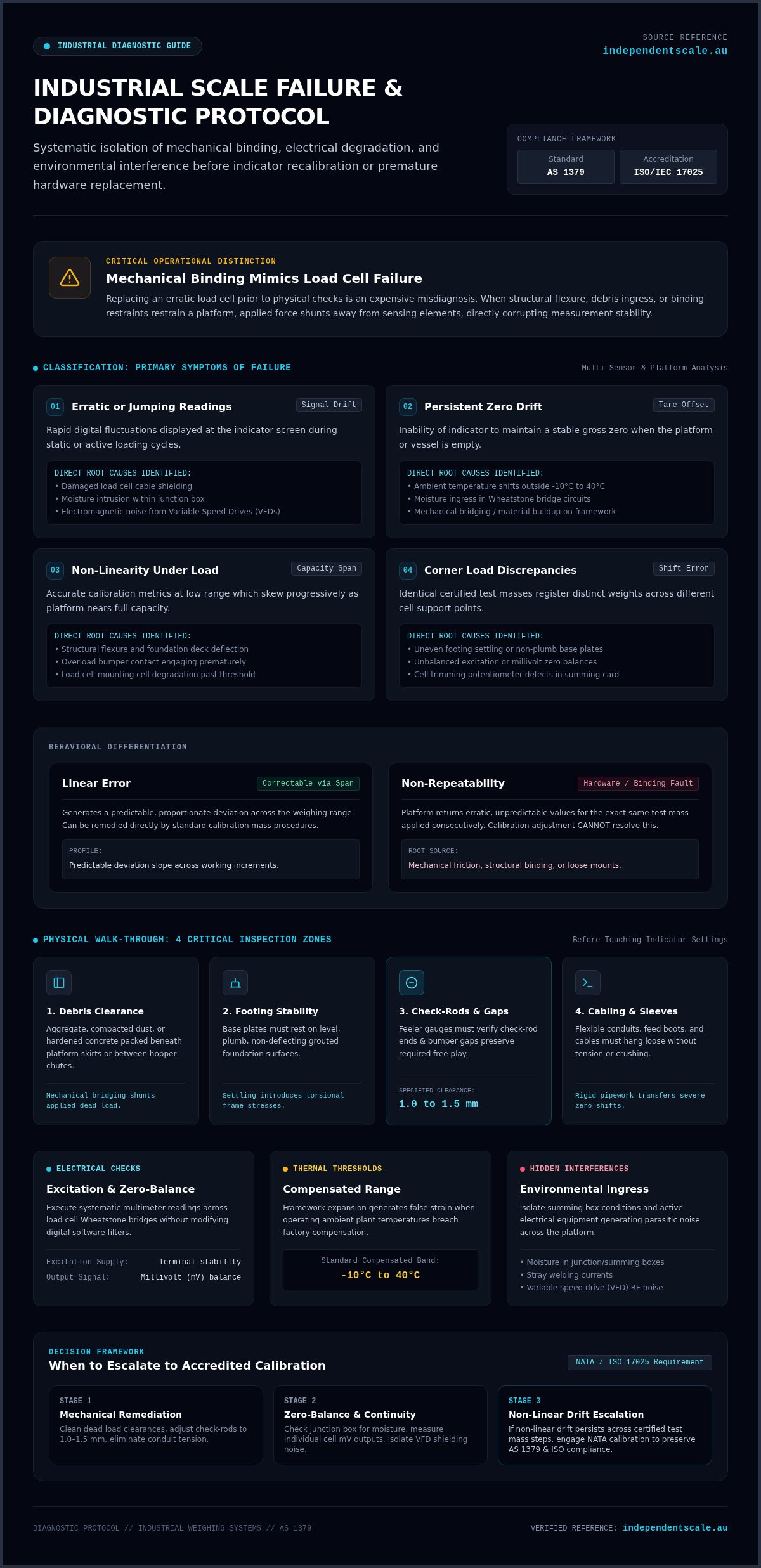
Industrial weighing systems operate under harsh mechanical loads, cyclic fatigue, and aggressive environmental exposures. When diagnosing an erratic weighing scale, consumer-grade troubleshooting fails because it overlooks structural deflection and multi-sensor load distribution. Effective troubleshooting common scale problems begins by classifying the exact operational symptom exhibited by your system, separating physical binding from internal electrical degradation.
Four primary failure symptoms indicate severe measurement issues across industrial platforms, hoppers, and weighbridges:
- Erratic or Jumping Readings: Rapid digital fluctuations, often caused by damaged load cell cable shielding, moisture within the junction box, or active electromagnetic interference from adjacent variable speed drives (VFDs).
- Persistent Zero Drift: The inability of the digital display to hold a stable gross tare when the platform is completely empty.
- Non-Linearity Under Load: Accurate measurements at low range that deviate significantly as platform loading approaches maximum capacity.
- Corner Load Discrepancies: Shift errors where an identical test mass registers distinct weights when positioned over different support points in a multi-cell array.
Zero Drift and Reading Instability
Zero drift occurs when an unloaded scale continuously accumulates or sheds weight values over time. Thermal expansion across steel framework often creates false strain against the sensors, particularly if ambient plant temperatures fluctuate outside the standard compensated range of -10°C to 40°C. Check the digital indicator's motion detection and zero-tracking parameters before recalibrating. If digital filtering cannot settle the reading, inspect for mechanical bridging or water ingress compromising the internal Wheatstone bridge circuits.
Inaccuracy and Non-Repeatability Across Weigh Cycles
Linear error differs substantially from non-repeatability. Linear error produces a predictable, proportionate deviation across the span, which standard span calibration can correct. Non-repeatability, conversely, means the platform returns unpredictable values for the exact same test mass applied consecutively. This erratic behavior points directly to mechanical friction, loose hardware, or structural binding beneath hopper mounts and platform decks. When conducting troubleshooting common scale problems, test the system across working increments using certified test masses to distinguish electrical zero-balance shifts from physical interference.
Step-by-Step Mechanical and Physical Scale Inspection
Mechanical binding accounts for a major percentage of apparent calibration errors in industrial processing plants. When structural flexure, debris ingress, or binding hardware restrains a vessel or platform, applied forces shunt away from the sensing elements. This mechanical shunting directly alters measurement uncertainty during operation. Before touching indicator calibration settings, technicians must conduct a physical assessment to confirm all load transmission paths remain completely uncompromised.
A rigorous physical walk-through covers four critical structural areas:
- Debris and Build-Up Clearance: Aggregate, compacted dust, or hardened concrete packed beneath platform skirts or between hopper discharge chutes mechanically bridges the dead load.
- Foundation and Footing Stability: Base plates must rest on level, plumb, non-deflecting grouted surfaces. Foundation settling transfers uneven torsional stresses across the base frame.
- Check-Rods and Restraints: Horizontal stay-rods and bumper bolts must keep vessels centered without introducing vertical friction during travel.
- Cabling and Enclosures: Flexible conduits and sensor cables must hang loose without tension, pinch points, or external crushing damage that could mechanically pull on the scale structure.
Checking for Mechanical Binding and Rubbing
Confirm proper operating clearances on hoppers, silos, and pit platforms. Use feeler gauges to verify that bumper gaps and check-rod ends maintain nominal clearance, typically 1.0 to 1.5 millimetres. Tight, bound rods generate severe non-repeatability by resisting vertical downward force. Flexible sleeves and product feed boots attached to vessels must remain pliable and free of caked product. Rigid pipework transfers substantial loads into the structure, creating unpredictable zero shifts across production runs.
Inspecting Hardware and Load Introductions
Examine the load introduction components beneath each support point. Rocker pins, upper load buttons, and hardened receiving cups must remain upright and centrally seated. Angular deflection or galling on bearing surfaces creates side-loading, which prevents the sensor from deflecting purely along its vertical axis. Check every mounting bolt with a torque wrench to ensure load cells have not shifted under shock loading. If retrofitting hardware or replacing damaged assemblies on process vessels, installing engineered tank silo weighing assemblies ensures correct load introduction and long-term mechanical stability. Systematic physical verification isolates structural friction from genuine sensor faults, streamlining the execution of troubleshooting common scale problems.
Electrical and Signal Diagnostics for Load Cells and Junction Boxes
When physical inspections confirm that mechanical assemblies move freely without binding, electrical faults represent the next diagnostic tier. A scale terminal relies on minute changes in millivolt potential generated across strain gauges. Slight signal degradation, loose terminal screws, or moisture tracking across a printed circuit card will completely destabilize the reading. Resolving these issues requires a logical process of elimination across the summing network.
Before disconnecting field cabling, verify stable terminal excitation. A calibrated digital multimeter set to DC volts should measure between 5V DC and 10V DC across the excitation terminals (EXC+ and EXC-), matching the terminal manufacturer's baseline specification. Fluctuating excitation voltage indicates an internal power supply fault inside the digital indicator rather than a sensor defect. Once stable excitation is verified, proceed through systematic electrical checks:
- Isolate Individual Sensors: Disconnect all load cells from the summing card, then measure each unit independently to locate the failing element.
- Measure Signal Output: Check signal lines (SIG+ and SIG-) with the scale empty to record the millivolt zero balance.
- Perform Signal Trimming Verification: In multiple-sensor configurations, verify potentiometer trim settings to ensure uniform signal reduction across all channels without clipping.
- Inspect Summing Card Pathways: Examine the printed circuit board for corrosion, track delamination, or heat-damaged bridge resistors.
Testing Load Cell Resistance with a Digital Multimeter
Disconnect the sensor completely from the junction box to evaluate bridge integrity against the original calibration certificate. Measure input resistance across EXC+ and EXC-, followed by output resistance across SIG+ and SIG-. Typical bridge values read either 350 ohms or 1,000 ohms, with acceptable manufacturing tolerances rarely exceeding ±1 to ±3 ohms. Next, measure the zero balance by powering the cell with regulated excitation; an unloaded sensor exceeding ±1% of full scale (typically >0.02 mV/V) indicates permanent plastic deformation from an overload event. Finally, conduct an insulation resistance test with a megohmmeter between all bonded conductors and the cable shield. Any reading below 5,000 megohms confirms moisture ingress inside the strain gauge cavity. When field measurements fall outside standard operational tolerances, professional load cell calibration or immediate replacement restores system integrity.
Diagnosing Junction Box and Moisture Ingress Faults
Harsh plant washdowns and diurnal condensation cycles frequently introduce moisture through compromised cable glands. Water sitting across terminal blocks creates high-resistance leakage paths, producing wild, erratic zero jumps. Inspect internal desiccant packs for saturation, replacing any spent indicator beads immediately. Inspect terminal screws for galvanic corrosion, which degrades low-level analog signals. If a terminal box shows water tracking, enclosure pitting, or cracked seals, replacing failed hardware with sealed, stainless industrial junction boxes and surge arrestors prevents lightning spikes and environmental ingress from recurring during routine troubleshooting common scale problems.
Environmental Interference, Calibration Drift, and Regulatory Limits
External industrial environments present severe operational challenges to weighing accuracy. Even when mechanical assemblies move smoothly and internal bridge resistances test clean, environmental noise and thermal forces can distort weight data. Systematic troubleshooting common scale problems requires identifying whether an anomaly stems from external plant interference, true seasonal drift, or irreversible component damage.
Industrial installations must routinely combat three significant ambient hazards:
- Radio Frequency Interference (RFI) and Electromagnetic Noise: High-frequency emissions radiating from unshielded Variable Frequency Drives (VFDs) or large conveyor motors inducing phantom voltage onto low-level millivolt lines.
- Ground-Loop Voltages: Potential differences between disparate earth points flowing through load cell braided shields rather than dedicated grounding paths.
- Direct Thermal Expansion: Solar radiation or process heat acting unevenly on large steel structures, inducing torsional stresses that register as weight shifts across fixed mounts.
Grounding, Lightning, and Electrical Interference
Every weighing vessel requires a continuous, low-resistance single-point earth bond to bypass dangerous current paths. In high-vibration plants, braided copper ground straps installed across each load cell mounting kit direct transient spikes safely to ground. Technicians must enforce strict protocols during site maintenance. Welding current seeking an earth return path through a load cell element will instantly vaporize internal foil strain gauges. Signal lines require steel conduit runs separated by at least 300 millimetres from high-voltage AC power lines to stop inductive noise coupling.
Calibration Drift vs. Hard Component Breakdown
Differentiating gradual calibration drift from permanent hardware deformation is critical for statutory compliance. Ambient temperature swings naturally cause minor zero shifts, which indicator auto-zero tracking can handle. Re-zeroing should never compensate for non-linear span loss or permanent zero shifts exceeding operational tolerances. Repeatedly pressing tare often masks cracked load buttons or bent shear beams. In regulated Australian production, such as ready-mix batching plants operating under AS 1379, weighing tolerances are strictly defined; cementitious materials, water, and aggregates must adhere to exact percentage tolerances across every batch cycle. Operating out of spec risks substantial project rejections and audit failures, with fines for non-compliant commercial measurement equipment exceeding A$10,000 in certain Australian jurisdictions. For facilities managing critical batch compliance, scheduling a certified concrete batching plant calibration verifies traceability to national measurement standards and prevents costly regulatory penalties.
When to Escalate: Professional Service and Accredited Calibration
Field diagnostics reach a hard boundary when internal bridge resistance shifts permanently or structural deflection exceeds physical limits. Continuing in-house calibration attempts on damaged hardware wastes valuable production hours and invalidates critical process warranties. Recognizing when site-level interventions can no longer restore weighing accuracy is the final phase of troubleshooting common scale problems.
Escalation to accredited service specialists becomes necessary under specific operating thresholds:
- Non-Recoverable Millivolt Output: The load cell outputs zero-balance voltages beyond ±1% of full scale under zero load, indicating irreversible mechanical yield.
- Persistent Insulation Breakdown: Megohmmeter readings between gauge circuits and cable shielding remain below 5,000 megohms despite thorough drying.
- Severe Linearity or Repeatability Failures: Incremental mass testing reveals non-linear deviations across working load steps that simple digital filtering cannot stabilize.
- Statutory Verification Requirements: Scales governed by commercial trade or quality standards require formal testing with traceable, certified reference standards.
Limits of In-House Repairs and the Risk of Non-Compliance
Modifying digital indicator calibration parameters to compensate for a mechanically compromised sensor introduces extreme commercial risk. According to NIST, a weight miscalculation of just 0.1% can lead to thousands of dollars in over- or under-filled product over time. Plant operators adjusting calibration without traceable reference masses compromise audit readiness under ISO 9001 quality frameworks. Production facilities subject to strict manufacturing standards must rely on NATA-accredited test protocols rather than unverified bulk material tests. Routine span adjustments cannot correct asymmetric corner loading; they simply shift measurement error to other working ranges, causing compound batch discrepancies.
Engaging Accredited Technicians for Immediate Remediation
Direct engagement with specialized technicians secures legally defensible compliance through ISO/IEC 17025 accredited calibration procedures. Service specialists deploy mobile test rigs carrying metric test masses traceable to national measurement standards, ensuring high-capacity platforms and vessels receive full-range proof loading. For heavy process vessels, scheduling a formal hopper calibration service establishes true mechanical linearity and eliminates product giveaway. When testing reveals irreparable strain gauge degradation, sourcing replacement hardware from a certified provider carrying extensive load cells stock guarantees rapid system restoration. Establishing structured preventative calibration contracts transforms emergency breakdown events into predictable, compliant maintenance cycles across Sydney, Melbourne, and regional processing facilities.
Restore Weighing Accuracy and Protect Plant Productivity
Systematic diagnostic workflows protect process facilities from unnecessary hardware replacement and costly batching shutdowns. By methodically eliminating mechanical binding, verifying summing cards for moisture tracking, and testing millivolt outputs against baseline tolerances, plant technicians can master troubleshooting common scale problems with absolute confidence. When zero balance drifts permanently or non-linear error compromises batch tolerances, accredited escalation guarantees measurement integrity before an audit fails.
Independent Scale Service provides NATA accreditation to ISO/IEC 17025 standards and complete compliance verification under AS 1379 concrete batching specifications. With rapid response field support across Sydney, Melbourne, and regional Australia, our technicians deploy calibrated mobile test equipment and comprehensive replacement hardware to resolve complex weighing faults immediately. Book NATA-accredited scale calibration and emergency repair today to secure verifiable accuracy across every production cycle.
Frequently Asked Questions
Why is my digital scale weight reading jumping up and down erratically?
Erratic weight readings typically stem from compromised cable shielding, unstable excitation voltage, or water ingress inside the junction box enclosure. High-frequency electrical interference from nearby variable speed drives or conveyor motors can also induce stray millivolt spikes across the signal lines. During troubleshooting common scale problems, inspect all terminal connections for tightness and verify that the sensor cable runs in dedicated earthed conduit.
Can moisture inside the junction box cause load cell zero drift?
Yes, ambient moisture or washdown condensation inside the summing card enclosure causes severe zero drift. Water forms conductive leakage paths across terminal block pins, lowering insulation resistance and disrupting the low-level millivolt balance of the Wheatstone bridge. If you notice weight creeping on an empty vessel, open the summing box, inspect for corroded terminals, and replace saturated desiccant packs immediately.
What is the difference between mechanical binding and a faulty load cell?
Mechanical binding causes non-repeatable errors and friction drag while the load cell's internal electrical bridge resistances remain perfectly intact. A faulty load cell exhibits shifted input or output bridge resistance, degraded insulation resistance below 5,000 megohms, or permanent zero shifts exceeding ±1% of rated capacity. Checking physical clearances with feeler gauges separates mechanical restriction from damaged internal strain gauge elements.
How do I test if an individual load cell is damaged using a multimeter?
Disconnect the sensor and measure input resistance across EXC+ and EXC-, then output resistance across SIG+ and SIG-. Compare the readings to the manufacturer's datasheet, looking for balance within ±1 to ±3 ohms. Next, power the cell with regulated DC excitation to confirm the zero-load millivolt output stays near baseline, and use a megohmmeter to ensure conductor-to-shield insulation exceeds 5,000 megohms.
Can welding on a vessel or chassis damage installed weighing scales?
Electric arc welding on a weighing vessel can instantly destroy installed load cells if current arcs across the internal strain gauges. When an earth clamp is positioned incorrectly, heavy welding current seeks the path of least resistance through the sensor's internal flexures to ground. Always disconnect signal leads, attach the earth clamp directly to the welded member, and install copper bypass ground straps across every mounting kit.
What should I do if an industrial scale will not return to zero?
Inspect the platform or hopper perimeter for aggregate buildup, bound check-rods, or rigid utility conduits restricting physical return. If the structure is free, evaluate the zero-balance millivolt output of each sensor under no load. A sensor showing residual millivolts well above manufacturer zero-balance tolerance suffered plastic deformation from an overload or shock event and requires replacement rather than repeated zero adjustments.
How often does an industrial production scale require NATA-accredited calibration?
Industrial weighing systems generally require formal verification every six to twelve months, depending on throughput, environmental severity, and statutory mandates. Regulated facilities producing concrete under AS 1379 must maintain documented calibration schedules to satisfy mandatory compliance audits. Securing calibration through a NATA-accredited provider to ISO/IEC 17025 standards ensures that measurement uncertainties remain defensible, traceable to national standards, and compliant with plant quality management protocols.
