


Load Cell Junction Box Troubleshooting: A Professional Diagnostic Guide
A 1% margin of error in a high-volume Australian concrete plant can result in over A$75,000 of product giveaway annually. When your weighing system begins to drift or fails to return to zero, the financial and regulatory stakes are too high for guesswork. Production downtime is costly, and the risk of non-compliance with the updated AS 1379:2026 standard can jeopardize your entire operation. Effective load cell junction box troubleshooting is the first line of defense in isolating whether a fault lies within a single sensor or the summing circuitry itself.
We understand that pinpointing a failing component in a multi-cell system is often the most frustrating part of industrial maintenance. This professional guide will help you master the technical steps to identify summing box faults and restore weighing accuracy. You'll learn how to perform critical electrical tests safely and determine if your system requires NATA-accredited recalibration to meet ISO/IEC 17025:2026 requirements. We provide a methodical diagnostic framework designed to minimize downtime and maintain the strict industrial compliance your business demands.
Key Takeaways
- Identify the junction box as the central summing point for multi-cell systems to streamline your diagnostic process.
- Detect moisture ingress and seal breaches early to prevent permanent circuit board damage and signal drift.
- Execute systematic load cell junction box troubleshooting by measuring excitation voltages and performing signal trimming to isolate faulty sensors.
- Resolve erratic readings by identifying electromagnetic interference (EMI) and implementing proper "star grounding" techniques.
- Understand the necessity of NATA-accredited recalibration after any hardware adjustment to ensure compliance with AS 1379:2026 standards.
Understanding the Role of the Junction Box in Weighing Systems
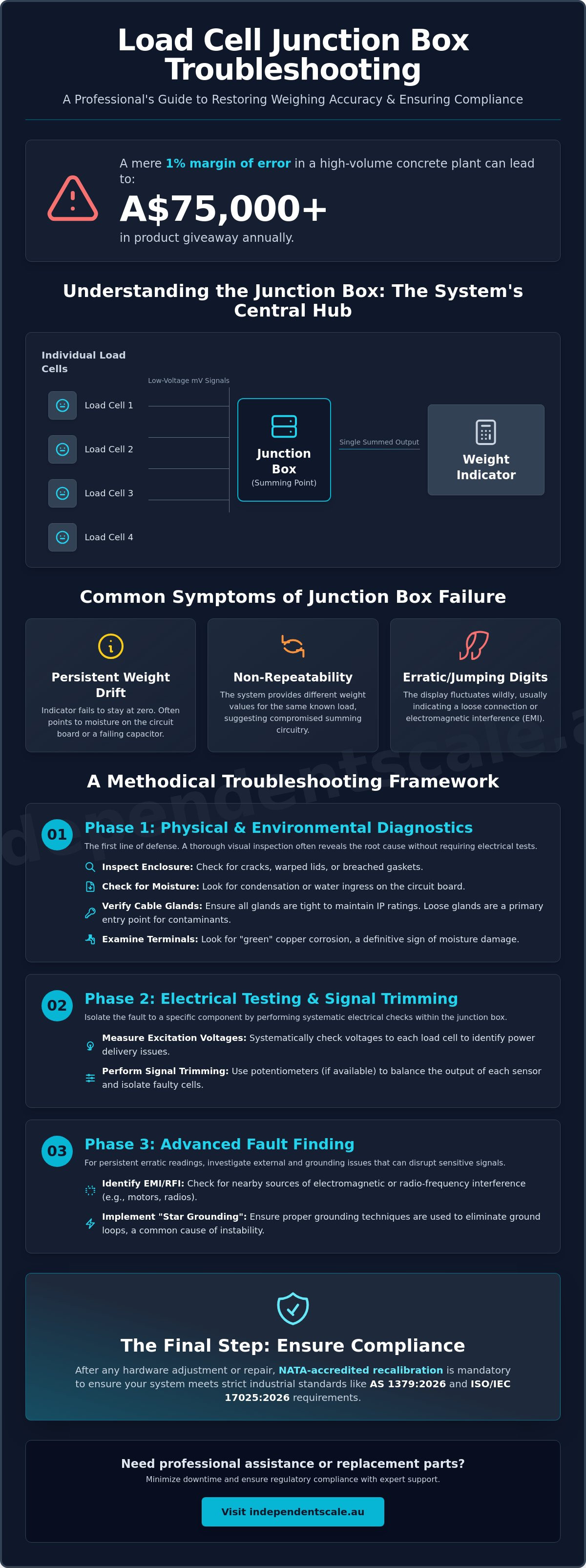
The junction box, or summing box, serves as the central hub for any multi-sensor weighing system. Its primary function is to aggregate the low-voltage millivolt signals from individual sensors and combine them into a single, cohesive output for the weight indicator. This process, known as signal summation, allows for the accurate measurement of large structures like hoppers, silos, and weighbridges. Understanding the Role of the Junction Box in Weighing Systems requires recognizing that this component is a critical link in the measurement chain. If the summing box fails, the entire system loses its ability to provide reliable data.
Most industrial systems utilize specialized junction boxes to manage these signals. There are two primary types: passive summing boxes and active trimming boxes. Passive boxes simply connect the load cells in parallel. Active trimming boxes include adjustable resistors, or potentiometers, which allow technicians to balance the output of each individual sensor. This corner adjustment is vital for ensuring that a load placed on any part of the scale produces the same weight reading. Exposure to harsh industrial conditions, such as constant vibration or moisture ingress, can degrade these internal components. This degradation is why load cell junction box troubleshooting is a priority for maintenance teams aiming to prevent production errors.
Key Components Inside the Summing Box
Inside the enclosure, several critical parts work together to maintain signal integrity. Terminal blocks provide the mechanical connection points for load cell wiring. These must remain tight and free of oxidation to prevent signal loss. Potentiometers are the adjustable components used during the calibration process to trim or match the output of each sensor. In outdoor applications, surge protection components are often integrated to protect the sensitive circuitry from lightning strikes or static discharge, which are common causes of sudden board failure.
Common Symptoms of Junction Box Failure
Identifying a fault begins with recognizing specific performance issues. Persistent weight drift, where the indicator fails to stay at zero, often points to moisture on the circuit board or a failing capacitor. Non-repeatability is another red flag. If the system provides different weight values for the same known load, the summing circuitry is likely compromised. Finally, erratic jumping digits on the display usually indicate a loose connection or electromagnetic interference within the box. Addressing these symptoms early through structured load cell junction box troubleshooting prevents the escalation of weighing inaccuracies and potential regulatory non-compliance.
Phase 1: Physical Inspection and Environmental Diagnostics
Effective load cell junction box troubleshooting begins with a rigorous physical assessment before any electrical meters are connected. In industrial environments, the enclosure is the primary barrier against failure. Technicians must first examine the housing for cracks, warped lids, or breached gaskets. Even a microscopic failure in a seal allows contaminants to enter, which eventually leads to catastrophic signal failure. Following this, check for moisture ingress or condensation on the circuit board. Condensation is particularly prevalent in Australian facilities where temperature fluctuations occur between day and night shifts, causing internal "sweating" that shorts out sensitive summing circuitry.
Maintain the system's IP68 or IP69K ratings by verifying that all cable glands are tightened. Loose glands are the most common entry point for water during high-pressure wash-downs. Examine every terminal connection for oxidation. "Green" copper corrosion on terminals is a definitive sign of moisture exposure and will significantly increase electrical resistance, leading to weight drift. Finally, inspect the desiccant pack inside the enclosure. If the pack is saturated or has changed colour, it's no longer protecting the internal components and must be replaced immediately. If you find significant internal damage, it's often more cost-effective to browse our range of industrial junction boxes rather than attempting to repair a compromised board.
Moisture and Corrosion: The Silent Killers
In the Australian climate, high humidity and aggressive cleaning chemicals create a perfect storm for corrosion. Once moisture enters a summing box, it creates parasitic loads across the terminal pins. This results in "ghost" weights or an indicator that won't stay at zero. While some operators attempt to use potting compounds to seal the board, this makes future repairs impossible. A better long-term solution involves upgrading to stainless steel enclosures with hermetically sealed entry points to ensure lasting reliability in harsh conditions.
Mechanical Stress and Cable Integrity
Cable integrity is just as vital as the box itself. Technicians should check for "wicking," a phenomenon where moisture enters a cut in the cable jacket and travels internally into the junction box. Regional Australian sites also face unique challenges from vermin. Rats and mice frequently chew through load cell cables, causing intermittent shorts that are difficult to diagnose without a full visual trace. Ensure all cable shielding is intact and properly grounded at the entry points to prevent electrical noise from entering the summing circuit. If your inspection reveals damaged sensors, you can find replacements in our load cell inventory to restore your system's integrity.
Phase 2: Electrical Testing and Signal Trimming Procedures
Once the physical integrity of the enclosure is confirmed, load cell junction box troubleshooting transitions to electrical diagnostics. Safety is the first priority; ensure the system is powered correctly and that you aren't creating accidental shorts across the excitation pins with your multimeter probes. Use a high-quality digital multimeter to measure the excitation voltage provided by the weight indicator. Most industrial systems operate on a stable 5V DC or 10V DC output. If the voltage at the junction box terminal is lower than the indicator's specification, you likely have a cable fault or a failing power supply within the indicator itself.
The Isolation Method is the most effective technical protocol for identifying a "bad apple" in a multi-cell system. Disconnect all load cells from the summing board and reconnect them one at a time while monitoring the indicator's stability and zero point. If the system remains stable with three cells but drifts or shows erratic digits when the fourth is connected, you've isolated the faulty component. During this process, interpret the millivolt (mV) output signals carefully. A healthy load cell at zero load should produce a signal very close to 0mV. For a 2mV/V sensor powered by 10V, the full-scale output is 20mV. Any reading significantly outside these expected ranges under known loads indicates internal strain gauge damage or a mechanical bind.
Using a Multimeter for Diagnostic Checks
Check for ground leakage by measuring the resistance between the shield wire and any signal wire. This insulation resistance should typically exceed 5,000 megohms; anything lower suggests moisture ingress or insulation breakdown. Next, verify bridge resistance by comparing input and output ohms against the manufacturer's datasheet. Common bridge values are 350 or 700 ohms. A deviation of more than a few ohms from the factory spec often points to a damaged bridge circuit. If the resistance is correct but the signal remains erratic, the fault may lie within the summing board's traces or the internal terminal contacts.
Corner Testing and Trimming Errors
Perform a "Shift Test" by moving a known test weight to each corner or support point of the scale. Variance between these positions indicates that the system's output is not balanced. If adjusting the potentiometers on the board doesn't change the output for a specific corner, the trimming circuit has failed, likely due to a burnt-out resistor or corrosion. Signal trim is the adjustment of output voltage to match cell sensitivities. If you can't achieve balance through standard adjustments, it's time to consider a professional load cell calibration to ensure the system meets regulatory standards. For sites managing complex setups, upgrading to high-quality junction boxes can simplify this balancing process significantly.
Advanced Fault Finding: Interference and Grounding
When physical inspections and basic electrical tests fail to resolve weighing errors, load cell junction box troubleshooting must pivot to identifying invisible electrical interference. In industrial settings, electromagnetic interference (EMI) is a frequent culprit. Nearby high-voltage motors, Variable Frequency Drives (VFDs), and even overhead lighting can induce parasitic currents into the sensitive millivolt signal lines. This interference doesn't always cause a total failure; instead, it often manifests as high-frequency "jitter" or erratic jumping of the digits on the weight indicator display. To combat this, a methodical "Star Ground" configuration is required. This ensures all system components share a single, common ground point, effectively eliminating the voltage differentials that lead to signal degradation.
Surge arrestors are another critical component in advanced fault finding, particularly for weighbridges or outdoor silos in lightning-prone regions. These boards are designed to sacrifice themselves to protect the more expensive load cells and indicators from high-voltage spikes. Diagnostic signs of a damaged surge protection board include visible charring on the circuit traces or discoloured Metal Oxide Varistors (MOVs). If you suspect a surge event has occurred, check the resistance between the signal lines and the ground terminal. A low resistance reading here indicates the protection components have partially shorted, which will bleed off the signal and cause significant weighing inaccuracies.
Grounding Loops and Shielding Failures
Ground loops are a common technical headache in complex weighing systems. They occur when the system is grounded at multiple points, creating a circulating current that mimics weight drift. To prevent this, the drain wire should typically be terminated at the indicator end only, remaining floating or isolated at the junction box. Use a multimeter to test the continuity of the shield through the summing board. If the shield is broken or incorrectly bonded at both ends, the cable acts as an antenna for ambient electrical noise. Ensuring a continuous, single-point shield is essential for maintaining the sub-millivolt precision required for industrial compliance.
Surge Protection and Lightning Damage
Visual signs of MOV failure, such as cracking or a "burnt" smell inside the enclosure, are definitive evidence of a surge event. While it might be tempting to bypass a damaged surge board to restore production, this is a high-risk temporary fix. Operating without active surge protection leaves your entire sensor array vulnerable to the next electrical spike. For facilities dealing with chronic noise or long cable runs, integrating conditioners and transmitters can provide superior signal isolation and boost the signal-to-noise ratio. If your system remains unstable after addressing grounding issues, contact us for a professional weighing scale calibration to verify the system's performance under load.
NATA Calibration and Professional Repair: Ensuring Compliance
Any hardware adjustment identified during load cell junction box troubleshooting fundamentally alters the system's electrical output. Whether you've replaced a single terminal block or a complete summing board, the original calibration settings are no longer valid. In industrial weighing, precision is not just an operational goal; it's a regulatory requirement. Independent Scale Service provides expert load cell calibration across Sydney and Melbourne, ensuring that your equipment meets the latest technical benchmarks. A professional recalibration confirms that the signal summation across all sensors is linear and accurate, preventing the costly product giveaway associated with unverified repairs.
NATA accreditation remains the gold standard for technical competence in Australia. For businesses operating under the ISO/IEC 17025:2026 standard, using an accredited laboratory is essential for maintaining quality control and safety. The updated NATA Calibration Annex, revised in August 2024, provides specific requirements for mass and related quantities that must be met to ensure traceability to national standards. Following any load cell junction box troubleshooting, a NATA-endorsed certificate serves as legal-for-trade proof of accuracy, which is vital for maintaining industrial compliance and protecting your business from the legal ramifications of inaccurate measurement.
When to Call a Professional Technician
Differentiating between a simple loose wire and a catastrophic board failure requires specialized diagnostic tools. While basic continuity tests are helpful, the risks of DIY trimming are significant. Adjusting potentiometers without certified test weights can lead to the loss of factory calibration settings, making the system non-compliant. Professional technicians possess the high-precision equipment needed to verify that your tank or silo weighing assembly is performing within specified tolerances. If the summing board shows signs of heat damage or if the signal remains erratic after physical cleaning, professional intervention is necessary to prevent further component failure.
AS 1379 Compliance for the Construction Industry
The construction sector faces stringent requirements under the AS 1379:2026 standard, which governs the specification and supply of concrete. For these facilities, concrete batching plant calibration is mandatory to ensure batching accuracy and structural integrity. Documented troubleshooting and repair logs are not just good practice; they are a core component of maintaining your NATA accreditation and meeting audit requirements. Independent Scale Service offers the technical expertise required to keep your plant operational and compliant. Contact us for expert on-site diagnostics and NATA calibration to restore your weighing accuracy and minimize production downtime.
Restoring Precision and Regulatory Compliance
Successful load cell junction box troubleshooting requires a methodical approach that balances immediate physical inspections with advanced electrical diagnostics. By isolating faulty components and addressing environmental vulnerabilities like moisture ingress or grounding loops, you protect your system from chronic drift and erratic readings. However, technical repairs are only the first step. To maintain industrial compliance and avoid the financial risks of inaccurate weighing, any hardware adjustment must be followed by professional verification.
Independent Scale Service provides the technical expertise and accredited certification necessary to keep your operations running within legal tolerances. Our team is NATA Accredited to ISO/IEC 17025 and offers AS 1379 compliant services to ensure your concrete batching plants and industrial scales meet the most rigorous Australian standards. We provide expert support across Sydney, Melbourne, and regional Australia to minimize your downtime and restore confidence in your measurement data. Don't leave your weighing accuracy to chance; ensure your system is fully optimized for performance and compliance.
Book a NATA-Accredited Diagnostic Service with our specialist team today to secure your operational accuracy.
Frequently Asked Questions
How do I know if my load cell junction box is bad?
Common indicators of a failing junction box include erratic weight displays, an inability to zero the scale, and non-repeatable readings. Visual evidence such as moisture on the circuit board, green corrosion on terminal blocks, or charred surge protection components provides definitive proof of failure. If your weight indicator shows a generic error but individual sensors test as healthy, the summing board is likely the source of the fault.
Can I bypass a junction box if only one load cell is failing?
Bypassing the summing box to operate a multi-sensor system with one cell missing is not a viable solution. This practice compromises the structural integrity of the scale and results in significant weighing inaccuracies. While you can disconnect a sensor during load cell junction box troubleshooting to isolate a fault, the system must remain offline until a replacement is installed and a full NATA-accredited calibration is performed.
What is the difference between excitation trim and signal trim?
Excitation trim balances the system by adjusting the input voltage reaching each individual load cell. Signal trim is more common in modern industrial summing boards and uses potentiometers to adjust the millivolt output from each sensor before it is aggregated. Both methods are designed to achieve corner balance, ensuring the indicator displays an accurate weight regardless of where the load is positioned on the scale.
How much mV output should I see from my junction box?
The total output depends on the sensor sensitivity, typically 2mV/V or 3mV/V, and the excitation voltage provided by the indicator. For a system with 2mV/V sensors and a 10V excitation, the full-scale output is 20mV. At zero load, the signal should be near 0mV. Any reading significantly higher than zero at rest suggests a mechanical bind or internal damage to a sensor bridge circuit.
Is it necessary to recalibrate after replacing a junction box?
Recalibration is mandatory following the replacement of any summing board or internal component. Every board has slight variances in resistance that fundamentally alter how signals are summed. To maintain compliance with the AS 1379:2026 standard or trade measurement laws, the system must be verified with certified test weights. Professional recalibration ensures the system remains accurate and legally compliant for industrial use.
What are the signs of lightning damage in a weighing system?
Lightning damage typically presents as a total system failure or "frozen" weight readings on the indicator. Physical signs include charring on the summing board traces, discoloured Metal Oxide Varistors (MOVs), or a burnt electrical smell inside the enclosure. Electrically, you'll often find a dead short between the signal lines and the ground. Surges often travel through cable shields, so inspect all insulation for signs of arcing.
How do I test a junction box with a multimeter?
Begin by measuring the DC excitation voltage at the input terminals to confirm the indicator is providing stable power, usually 5V or 10V. Measure the millivolt output of each individual cell at the terminal blocks to check for balance. Comprehensive load cell junction box troubleshooting also requires testing for ground leakage by measuring resistance between the shield and signal wires, which should typically exceed 5,000 megohms.
Why is my scale reading drifting even after I zero it?
Persistent weight drift is frequently caused by moisture ingress or temperature fluctuations affecting the summing board. When humidity enters the enclosure, it creates parasitic electrical paths that the indicator interprets as a changing load. Inspect the desiccant pack and seal integrity immediately. Drift can also result from a failing load cell or a loose ground connection that allows electrical noise to interfere with the low-voltage signal.
